

TECHNOLOGY
From a Concept to Reality by highly innovative technology
MOLD FLOW SIMULATION
MOLD FLOW SIMULATION
Please click each step on the left menu to see more information.
Please click each step below to see more information
1.0 Make 3D Printer
3D PRINTER - PRODUCTS OF SHIN-EI GROUP
To achieve qualified product, we start from creating a sample of 3D printer by considering the design proposal and its actual parts in detail rather than merely relying on a drawing and 3D data.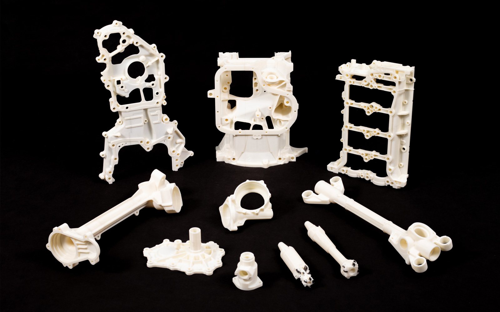
2.0 Make 3D Product Drawing
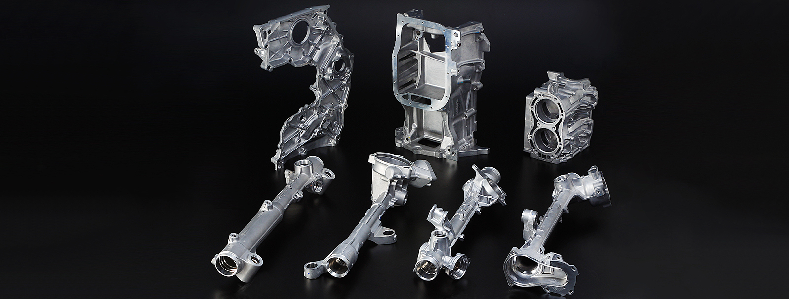
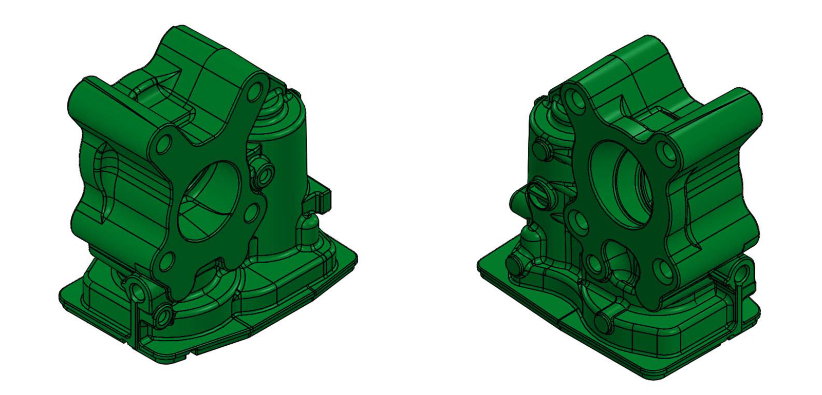
3D DRAWING PRODUCT - CASTING
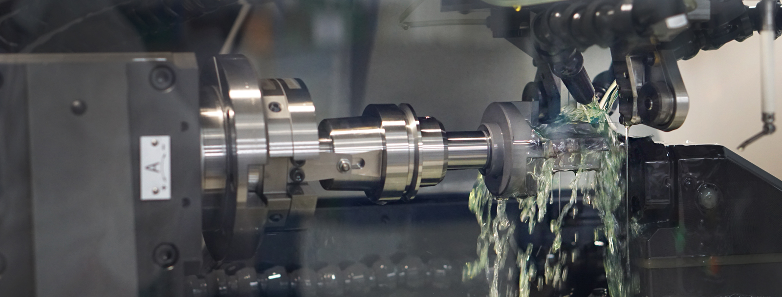
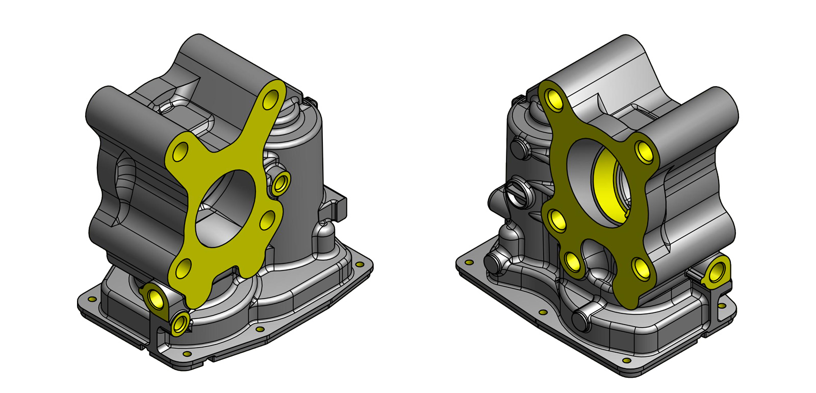
3D DRAWING PRODUCT - MACHINING
3.0 Mold Drawing by 3D Designed
3D MOLD DESIGN FOR SIMULATION
The analysis by 3D mold design『Mold is the most significant part for diecasting!』
3D mold drawing leads to an effective analysis as further details shown below :
(1) Flow Simulation (2) Solidification Simulation (3) Mold Temperature Simulation
In doing so, we can eliminate defect before making mold
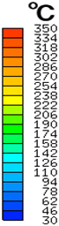
4.0 Mold Flow Simulation
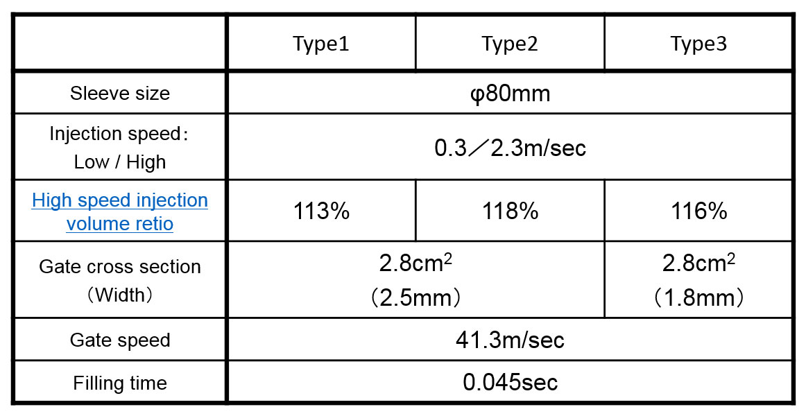
DC FLOW SIMULATION
Analysis by 3D mold design for Main Gate design
We make several possible choice for Main gate design simulation to find most optimized mold design for aluminum run characteristic.
We make several possible choice for Main gate design simulation to find most optimized mold design for aluminum run characteristic.
4.1 Mold Flow Simulation
DC FLOW SIMULATION
Analysis of 3D mold design for aluminum flow simulationWe make several possible choices for Main gate design simulation to find most optimized mold design for aluminum run characteristic.
4.2 Mold Solidification Simulation
DC SOLID SIMULATION
Analysis for solidificationUnsolidified area is displayed in blue color while isolated unsolidified area is marked in red color. Both areas is unable to supply aluminum effectively, resulting in shrinkage porosity.
4.3 Remaining Air Simulation
DC REMAINING AIR SIMULATION
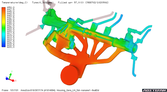
4.4 Mold Temperature Simulation
DC MOLD TEMPERATURE SIMULATION
Analysis for Mold temperatureTo balance mold temperature is very important to prevent overheat inside mold and also to maintain and keep die casting condition to be stable.
(1) Continuous cooling in green, (2) Timer controlled cooling in red and (3) Jet cooling are used
Moving Insert
■ : Cooling1 continuous
■ : Timer control
■ : Timer control
Analysis for Mold temperature balance in color identification
To visually check the balance of temperature inside an overheated area of mold can be identified through the color of temperature below. This potentially helps to find out the problem of temperature that consistently occurred during the shot cycle of the first injection until the process of opening mold.
Moving Insert
4.5 Summary of Casting Simulation
DC MOLD SIMULATION
Design Review to customerAfter summarizing the result of analysis performed by casting simulation, We propose design review to customer before we kick off the fabrication of mold as below to achieve the best design for cast quality :
(1) Reduce material (2) Add squeeze pin (3) Additional over flow (4) Additional gate
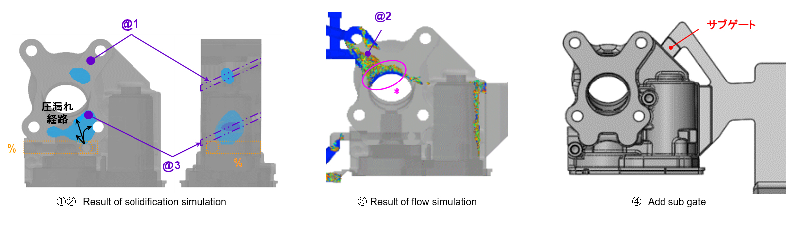
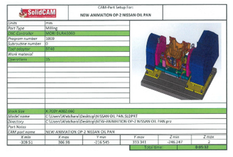
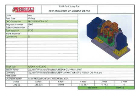
5.0 Cutting Tool and Machining Jig by 3D Designed
CUTTING TOOL AND MACHINING JIG BY 3D DESIGNED
3D Designed Jig and cutting tool for simulation of sophisticated machining conditionTo achieve most effective machining concept , 3D designed jig and cutting tool is enable to find the best condition of machining by using simulation software to prevent potential problem.
(1) Zero intervention of Jig and cutting tool, (2) effective machining process, (3) Accurate cycle time
5.1 Cutting Tool and Machining Jig by 3D Animation
CUTTING TOOL AND MACHINING JIG BY 3D ANIMATION
3D Designed Jig and cutting tool for simulation of sophisticated machining conditionTo achieve most effective machining concept , 3D designed jig and cutting tool is enable to find the best condition of machining by using simulation software to prevent potential problem.
(1) Zero intervention of Jig and cutting tool, (2) effective machining process, (3) Accurate cycle time
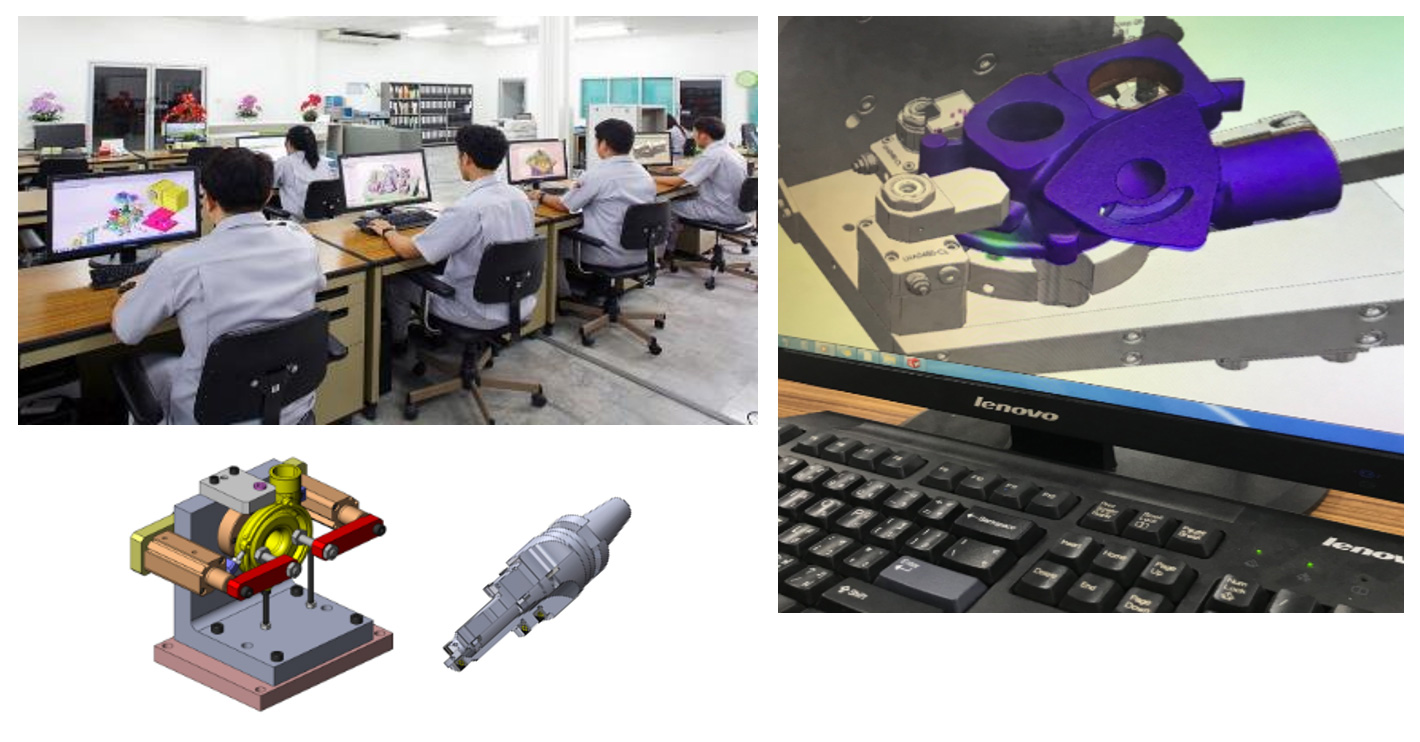
6.0 Machining Concept Simulation
MACHINING CONCEPT SIMULATION
Advantage of 3D design1. Can check MC program by software.
2. Can check interference of jig and cutting tool by software.
3. Can check stress of machining load.
4. Can check displacement of machining.
5. Can balance of clamping area for machining datum by software.
6.1 Machining Cycle Time Simulation by Software
MACHINING CYCLE TIME SIMULATION BY SOFTWARE
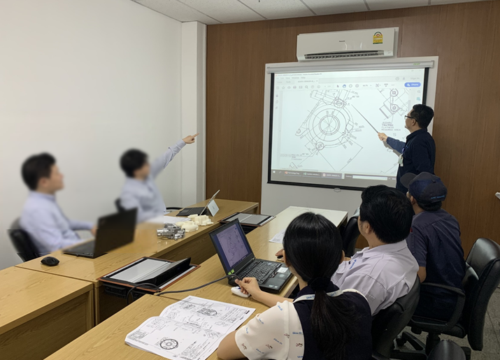
7.0 Design Review with Customer
DESIGN REVIEW WITH CUSTOMER
Request of design review :
Casting
● Reduce material.
● Increase radius for better casting quality.
● Change shape.
● etc.
Machining
● Machining concept review.
● Tolerance of machining review for better guaranteed of total quality.
● Machining metrology review.
● Leak and assembly specification review.
Casting
● Reduce material.
● Increase radius for better casting quality.
● Change shape.
● etc.
Machining
● Machining concept review.
● Tolerance of machining review for better guaranteed of total quality.
● Machining metrology review.
● Leak and assembly specification review.
8.0 Guaranteed by 3D Scanner / CT Scanner
PRODUCT GUARANTEED BY SIMULATION SOFT AND CT SCAN
Adstefan SCAN
SHIN-EI always examines our product with mold simulations to achieve designing meticulous casting features and to ensure that our design is robust before fabricating mold.
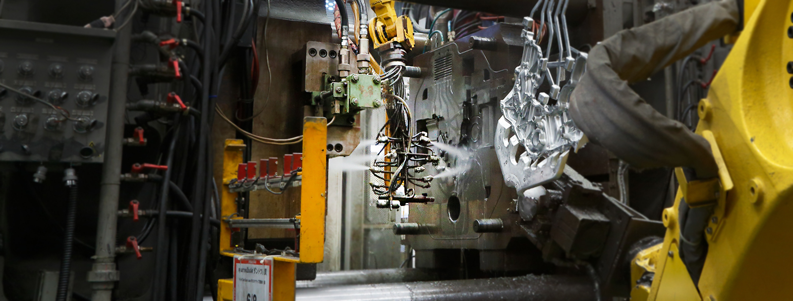
Before production, our engineer uses industry leading gate and runner design techniques to determine the best point to inject molten metal into a die, ensuring that you receive finished parts with the best density and structural features possible.
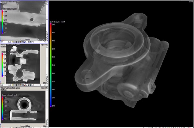
CT SCAN
SHIN-EI utilizes the CT scan to ensure internal quality of our product which helps to eliminate porosity. We also scrutinize the aluminum infrastructure for analysis, improvement, and our continuous KAIZEN.
SHIN-EI utilizes 3D scanner Technology for precise accuracy to improve production quality output and to prevent production downtime.